© 2004, 2005, 2006, 2007 by Man of the Cloth Productions
The information posted here is not intended as an explanation of how others can convert a power supply. Power supplies from all personal computers contain electrical hazards and can be dangerous. They contain current that can shock. The shock may cause bodily harm and or serious injury. Opening a power supply cover voids any remaining warranty. No one unfamiliar with power supplies should open or modify a power supply. work on the inside of a power supply when the power cord is connected to electricity. Every power supply is different. The color code of wires, the total output in watts, and the amperage of the DC varies from unit to unit. This is only what I did with one particular power supply. No applicable information, claim, guarantee, advice, or guidance is given or implied in the following...
I had an old computer power
supply. I think it was an ATX style supply. The label showed the
following ratings: Max 200 watts from all combined outputs. DC volts
output are rated at +5, -5, +12, -12, and +3.3. I wanted to see if I
could convert the power supply for use in my Zephyr or as a bench top DC
power supply to test some of my DIY projects.

The first step was to see if I could get the old switching supply to power up. Most PC switching power supplies require a load on the +5v DC line to power up. If this load is not found, the power supply (PS) will shut off because of built-in safety features. The easiest test was to plug in an old hard drive. But before it would power up, I needed to complete the circuit that went to the computer switch.
To do this I found the "Power Supply On or PS-On" wire. In most wire harnesses this is a green wire, located at pin 14.

It was for this power supply, too.
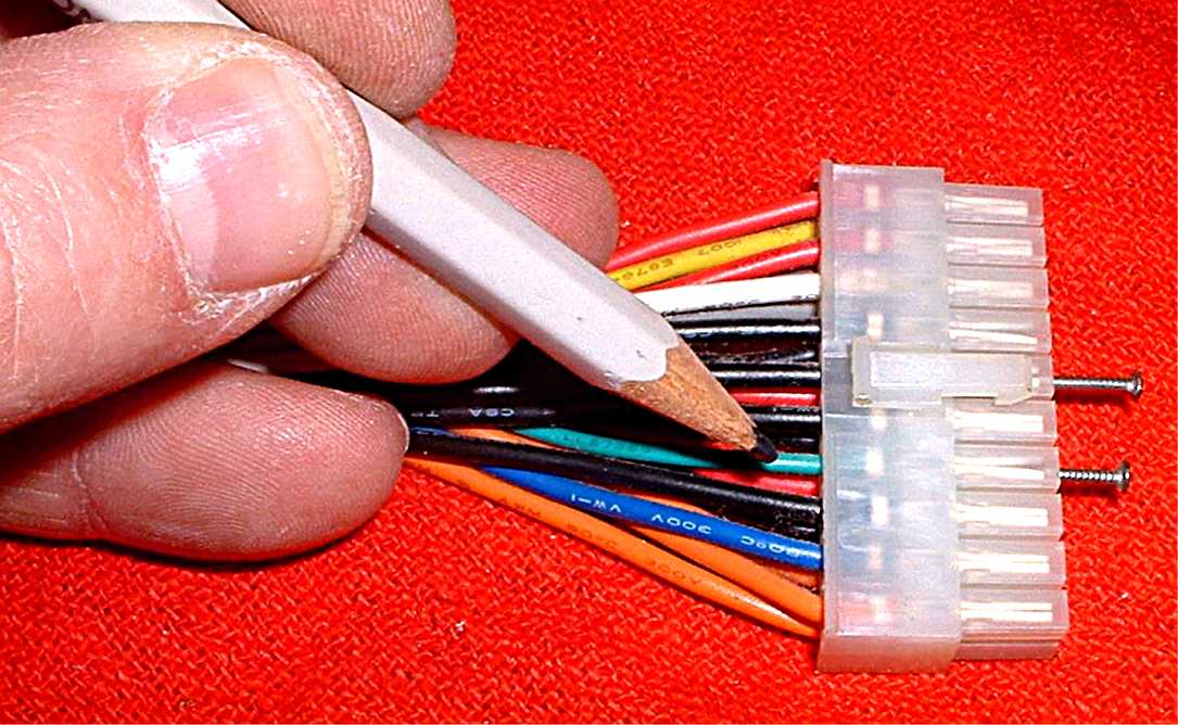
I slipped a small nail in the plug socket that corresponded to the green wire
and did the same for a black ground wire. Attaching a small alligator
clip across these nails completed the circuit for the "Power On" wire.
Next I attached the AC power
cord. The PS fan came on and the hard drive began to make "boot
up" sounds. I had a working power supply! While the PS was
working I tested the current coming from a red wire with my voltmeter. It
showed +5 v DC.
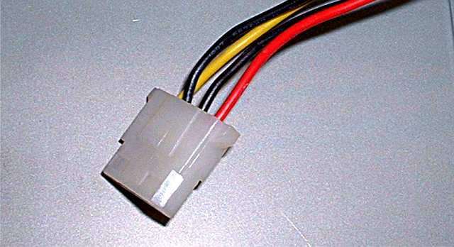
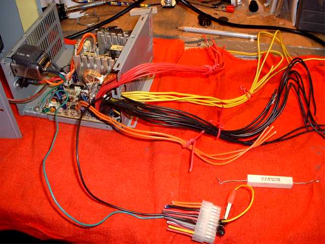
I turned the power off. My next step was to "trick" the PS into powering up under a load provided by a few resistors, without the hard drive attached. I selected one of the plugs with the following colored wires: yellow, black, black, red.
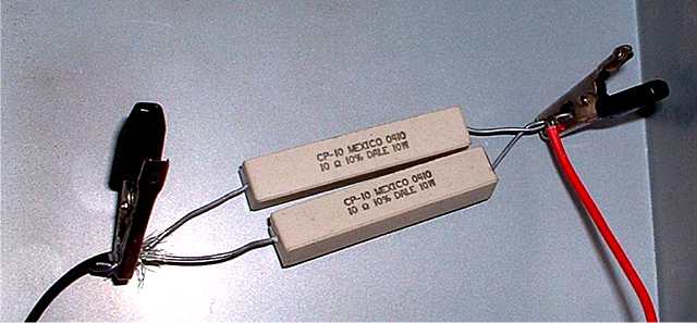
I cut the red and black wire from this plug and attached 2 10 ohm,
10 watt resistors wired in parallel. This was to simulate a load on this
circuit. The red wires supplied +5v DC.
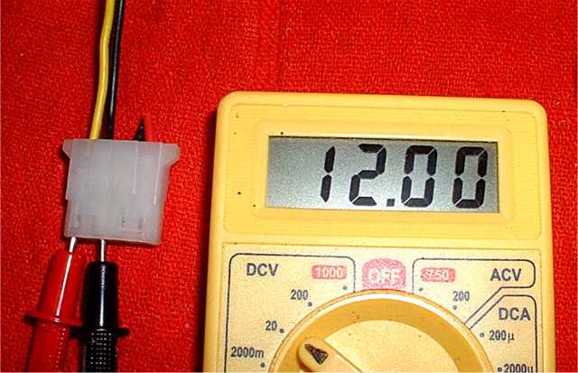
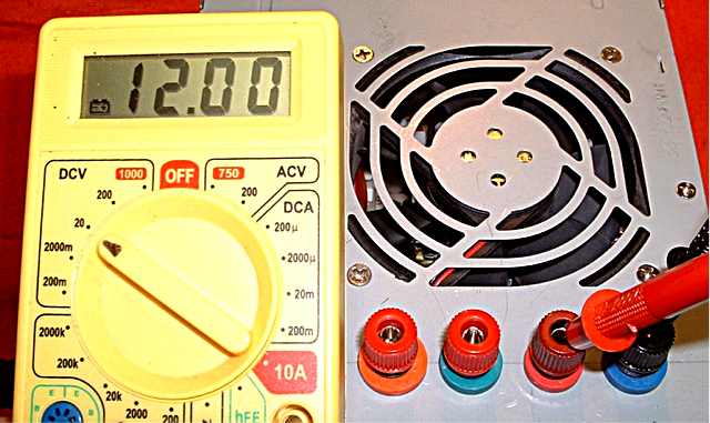
When the power cord was plugged
in again, the fan came on, even though the hard drive connection was removed
this time. I used my voltmeter, set at 20, and tested the voltage
coming out of the yellow circuit. It showed 12 v DC. Right on the nose!
Just what I wanted.
At this point, I checked the voltage in the other circuits. Each time I put the
black probe in a plug socket for a black wire (ground), and used the red probe
to test voltage of the other wires: red was +5 v DC, orange was +3.3 v DC,
and I already knew that yellow was +12 v DC. I wasn't interested in
negative voltage so I ignored other wires like blue, purple etc. So
far so good.
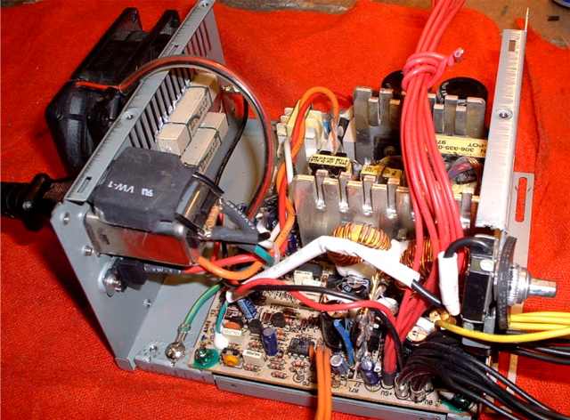
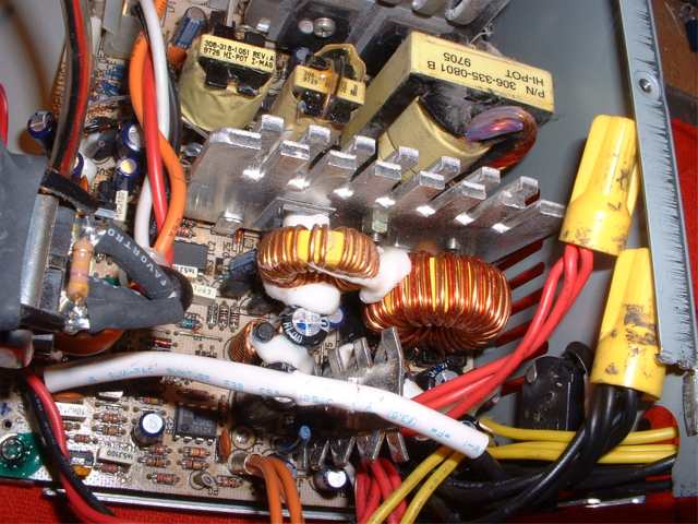
I unplugged the AC power cord and waited ten minutes for the capacitors to discharge. Then I took the cover off the unit for the first time. I cut away all computer plugs, as well as wires that were not red, yellow, orange, or black. (I did keep the green "Power On" wire. In the photo the green appears as a funny color.) I bundled all red, yellow, orange and black wires together by color. This made it easier to work with the unit.
I kept the green wire and one
black wire separated. These were the two wires that I previously used to
power up the unit by closing this circuit. Later I attached these to
a switch for easy on/off control. While the cover was off I disconnected
the fan and cleaned it.
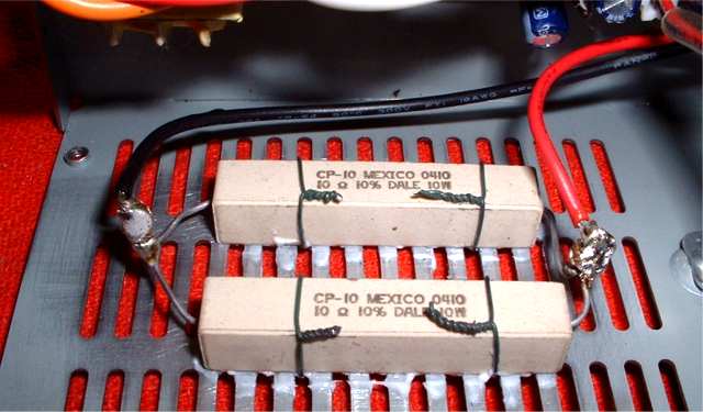
My next step was to install the
resistors. I found a place on the cover grill where the two resistors
could be mounted. I applied heat sink compound on the side of each
resistor that was most flat and wired them to the grill. This placement
will keep the resistors cool. Next I soldered a ground and a +5v
wire to the resistor leads, wired in parallel. For added safety the
resistor leads need to be insulated so they do not ground to the cover.
Then I installed a switch. The switch was rated at 10 amps. I took the green "Power On" wire and soldered it to one lead from the switch, and did the same with the black ground wire that I set aside for this purpose.
An old washer made the installation a snug fit. I covered these solder connections with heat shrink insulation to avoid a short.
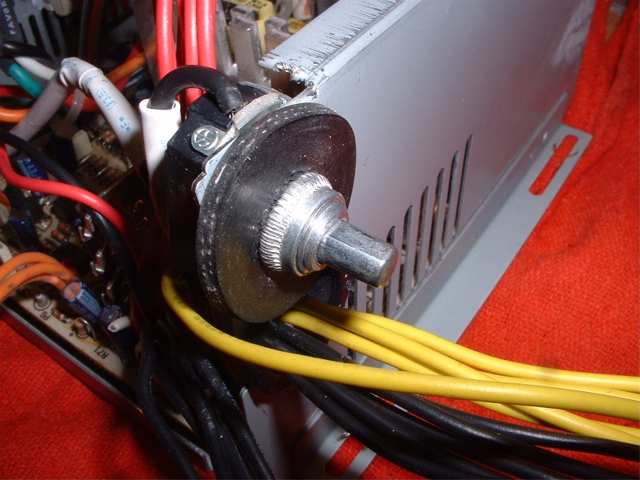
I covered these solder connections with heat shrink insulation to avoid a short.
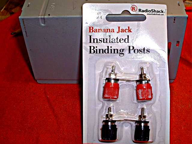
I purchased some Banana Jacks
from the store. Since I plan on having +12 v, +5 v, and +3.3 v I need
three red posts.
I plan on using one black post to
ground all circuits I test on this bench top power supply.
I located the
position of these posts on the top of the cover, making sure they would not
short to any of the power supply circuits. I drilled holes and
insulated the posts with household plumbing washers on top and a sheet of
insulation below.

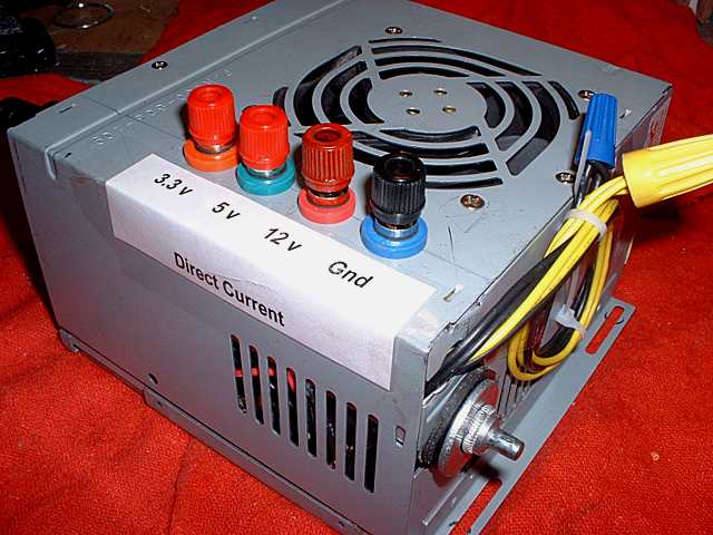
As you look at the
picture the voltages will be (left to right) 3.3 v DC, 5 v DC, 12, v DC,
and common ground.
Next I soldered connectors to the wires I wanted to connect to the bottom of the posts. I made sure that the wires were cut to length and the installation was neat.
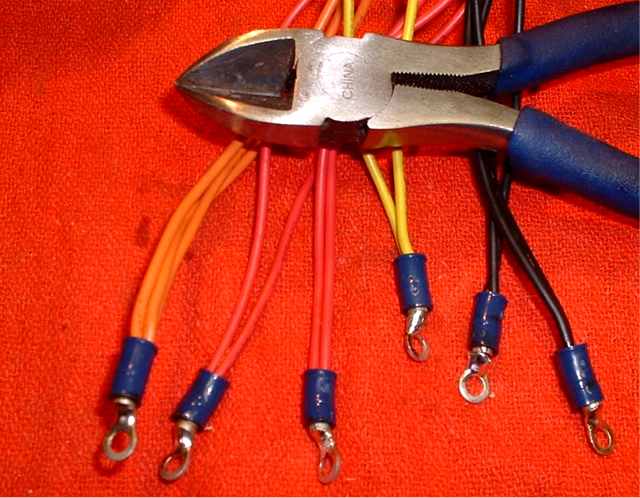
Extra red and black wires were cut off and capped with wire nuts.
You can see a few
yellow 12v DC and ground wires exiting the housing in the bottom right of the
photo above. I am keeping these to supply 12 v DC through a direct wire
connection.
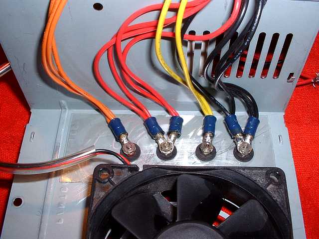
I placed the fan
back in its original spot with the same direction of air flow and replaced the
cover.
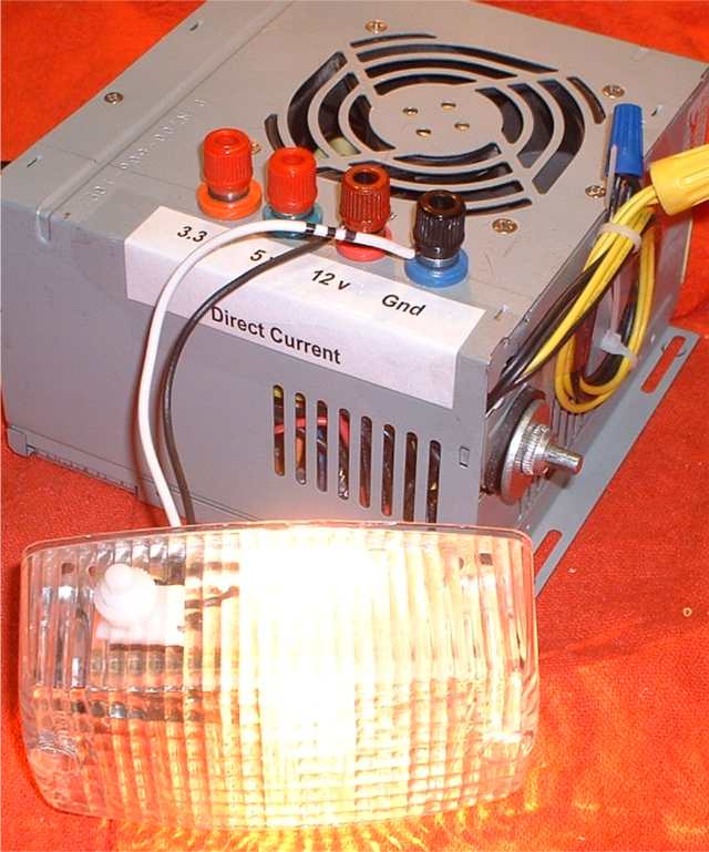
To finish the project I installed labels to mark the various voltages.
It worked for me. That's what made this a nice afternoon DIY project.
Parts List
Project cost: approx $8.00
The idea of this project is not original with me. Many other web pages have shown what other people have done to modify a PC Power Supply. If you check them out you will see several approaches.
Remember, there are
inherent risks and hazards in working with electricity. You alone are
responsible for all aspects of personal and material safety if you make any
application of this information. Always
check with a qualified electrician if you have any electrical
questions.
Links to other PC Power Supplies Projects
http://www.mattsrcstuff.com/PCPS.htm
http://www.marcee.org/Articles/PCPowerSupply.htm
http://www.epanorama.net/links/psu_computer.html
http://web2.murraystate.edu/andy.batts/ps/POWERSUPPLY.HTM#POWER_OK
http://www.qsl.net/i0jx/pcsupply.html
http://www.webx.dk/oz2cpu/radios/psu-pc1.htm
http://www.qrp4u.de/index_en.html
http://www.qsl.net/aa3sj/Pages/PC-Supply.html
http://cma.zdnet.com/book/upgraderepair/ch08/ch08.htm
Comments welcome.
Please visit this sponsor